
Type:
HM080S010
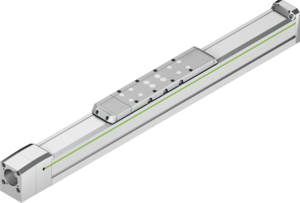
Abmessungen
Kritische Drehzahl n über Hublänge Achse LST
Durchbiegung w über ungestützte Achslänge LAW unter Nutzlast
| Dimensions | |||
|---|---|---|---|
| Lc | Total carriage length | 515 | mm |
| A | Cover strip deflection | 45 | mm |
| B | Switch position | 100 | mm |
| C | Switch position | 370 | mm |
| D | Clamp housing | 15 | mm |
| E | End position at mechanical zero | 68 | mm |
| F | End position at mechanical zero | 42 | mm |
| LT | Total length | LT = LST + 665 | mm |
| Load data | |||
|---|---|---|---|
| Fydynmax | Ultimate force | 4000 | N |
| Fzdynmax | Ultimate force | 8686 | N |
| Mxdynmax | Maximum torque | 67 | Nm |
| Mydynmax | Maximum torque | 1352 | Nm |
| Mzdynmax | Maximum torque | 623 | Nm |
| z | Upper carriage edge to guiding centre | 68,5 | mm |
| General technical data | |||
|---|---|---|---|
| Max. stroke | 3835 | mm | |
| vmax | Max. speed | 0,5 | m/s |
| amax | Max. acceleration | 15 | m/s² |
| Fx_max | Max. feed force | 3149 | N |
| Ma_max | Max. drive torque | 5,36 | Nm |
| Load capacity | 60 | kg | |
| Maximum total length | 4500 | mm | |
| Repeatability | ± 0.02 | mm | |
| Ix | Area moment of inertia of profile cross-section | 1293796 | mm⁴ |
| Iy | Area moment of inertia of profile cross-section | 1759898 | mm⁴ |
| Guiding | |||
|---|---|---|---|
| Guiding type | QHH20CA | ||
| Cdyn | Dynamic load rating | 30000 | N |
| C0 | Static load rating | 33860 | N |
| Drive | |||
|---|---|---|---|
| Shaft nominal diameter | 20 | mm | |
| Lead | 10 | mm | |
| Axial play | 0,02 | mm | |
| Cdyn | Dynamic load rating | 17100 | N |
| C0 | Static load rating | 33600 | N |
| Mechanical properties | |||
|---|---|---|---|
| Carriage mass | 3,08 | kg | |
| Mass at 0 stroke | 10,92 | kg | |
| Mass per 1 m stroke | 10,72 | kg/m | |
| Jrot. | Mass inertia moment at 0 stroke | 1,14 | kgcm² |
| Jrot. | Mass inertia moment per 1 m of stroke | 1,23 | kgcm² |
| Idle torque at 0 stroke | 0,52 | Nm | |
Carriage
HIWIN spindle axes are available with two different carriage lengths depending on the size and dimensions of the load to be transported. In order to ensure ideal, reproducible alignment of the adjacent structure, each threaded hole has an additional bore hole via which the load capacity can be fixed with centring sleeves. The matching centring sleeves can be found in the accessories.
Motor connection and belt drive
The multi-part design of the motor/gearbox adaptation creates an extremely flexible drive interface for the attachment and conversion of the drive technology. Optionally, the motor attachment can be rotated 180° via a belt drive, which significantly reduces the overall length. You can configure a suitable drive adaptation for your axis here.
Cover strip
The steel cover strip prevents dirt and dust from entering the axis interior. In addition, the cover strip allows the axes to be used in areas with coarse, sharp-edged or hot foreign bodies. The magnetic strips integrated in the axis profile hold the belt securely in position and increase the sealing effect.
Spindle support
In applications with long travel distances and high velocity, the critical speed of the shaft is quickly reached, meaning an appropriate support is required to prevent the shaft from swinging up. In HIWIN spindle drive axes, up to three travelling shaft supports can be installed on each side of the carriage. This allows driving at full speed, even with large strokes.
Lubrication
For convenient maintenance of the linear axis, a separate grease nipple is fitted to the left and right of the carriage for each lubrication point. This ensures optimum accessibility for relubrication, even under difficult installation conditions. For further information on lubrication and maintenance, please refer to the assembly instructions.
Spindle lead
The integrated HIWIN ballscrews ensure precise positioning thanks to their high pitch accuracy and rigidity. Different shaft pitches are available for each size in order to optimally meet the requirements for feed force and dynamics.
| Description | Category | Product | Size | Language |
|---|---|---|---|---|
| Linear axes and axis systems HX | Catalogue | Linear axes & linear axis systems | 13 MB | |
| Linear axes HM, HT, HB, HD | Project planning sheet | Linear axes & linear axis systems | 305 KB | |
| Spindle axes HM-S, HT-S | Assembly Instructions | Linear axes & linear axis systems | 4 MB |
HIWIN HX: Eine Achs-Familie – unzählige Möglichkeiten
Ein innovatives Design, zwei Bauformen, drei Antriebsarten und unzählige Möglichkeiten. Das flexible HIWIN-Achssystem HX bietet die passende Lösung für Ihre Ideen.
Montage der Endschalter und Einstellen des Schaltabstands bei HIWIN-Linearachsen
Die Endschalter oder zusätzliche Referenzschalter sind bei HIWIN-Linearachsen schnell und einfach montiert und stufenlos positioniert. Der Schaltabstand zum Bedämpfungselement lässt sich leicht mit Hilfe einer Fühlerlehre einstellen. In diesem Video zeigen wir Ihnen, wie es geht. Empfehlung Werkzeug/Hilfsmittel: 6-Kant-Winkelschraubendreher-Satz, Fühlerlehre, Maßstab, Montageanleitung.
Abdeckbandwechsel bei einem Linearmodul HM
Das Abdeckband lässt sich bei HIWIN-Linearmodulen HM schnell und einfach wechseln. In diesem Video zeigen wir Ihnen, wie es geht. Empfehlung Werkzeug/Hilfsmittel: 6-Kant-Winkelschraubendreher-Satz, Schnittschutzhandschuhe, Permanentmarker, Winkel, Blechschere, fusselfreies Tuch, Montageanleitung.